Getting started with ALINT-PRO
Table of Contents
Design Analysis Phases Overview
Creating Workspace and Project
Global Preferences and Project/File Properties
Introduction
This application note gives a basic introduction on how to start working with ALINT-PRO, it familiarizes you with the major features of the product and helps to bring the GUI into use.
Use of ALINT-PRO for functional verification on the early project stages makes the RTL design closure highly efficient. The primary purpose of applying ALINT-PRO is the Design Rule Checking (DRC) for the RTL code written in VHDL, Verilog and SystemVerilog design subset before running the logic synthesis phase. The rules cover typical coding mistakes, inconsistent coding style and limited code re-use, sub-optimal synthesis, synthesis vs simulation mismatches, non-portable coding practices, improper clock and reset networks, unsynchronized clock domain crossings, and many more topics.
Running the HDL designs in ALINT-PRO comprises of two key workflows: design entry and linting.
The design entry workflow divides into "parse", "elaborate", "synthesize", and "constrain" phases. The linting workflow splits into "parse linting", "elaboration linting", "synthesis linting", "constraints linting", and "chip linting" phases. All these phases verify that the design implementation conforms to the configured rule policy. The design entry workflow is linear: each subsequent phase can only be executed after the preceding phase succeeds. On the contrary, any of the linting workflow phases can be run in any order assuming that the corresponding dependent design entry phase has already succeeded.
The result of the design analysis by ALINT-PRO is a database of rule violations, where the user can query the detailed information about the identified issues, their origin in the RTL code, the descriptions of the issues, and documentation on the violated rules. ALINT-PRO provides instrumentation to filter the violations matching certain criteria, to re-configure the policy to adjust the behavior of the rules to the designer's style and needs, to setup waivers for the irrelevant issues, and to generate reports for the external review outside the linting tool. ALINT-PRO supplies a set of powerful GUI-based features to organize cross-probing between the violations, RTL source code and, where applicable, the schematic representation of the extracted high-level netlist.
Design Analysis Phases Overview
This section describes each phase of the design entry and linting workflows in detail.
The parse design entry phase performs syntax analysis of VHDL and Verilog/SystemVerilog sources, validates whether the input description conforms to the language reference manual and reports any possibly encountered syntax errors. Then it builds a non-elaborated HDL parse tree for each specified design unit and finally it saves the binary representation of the available units into the target library. A special window - Library Viewer - displays the contents of the resulting libraries.
Parse linting phase applies both to the basic syntax issues (use of comments, code formatting, preprocessing directives) and the non-elaborated HDL parse tree (use of particular language constructs). This is the simplest form of linting, where the rules directly handle the RTL code in the exact form as it is written in the source files without any transformations.
The elaboration phase executes the static design elaboration procedure, i.e., binds instances to design units, resolves library references, unrolls generate statements and computes generic-dependent expressions, checks all hierarchical names, etc. The result of the elaboration phase is an elaborated HDL parse tree and the design instances hierarchy, which can be observed in the Elaboration Viewer window. The elaboration can be run with the automatically identified as well as with the manually specified top-level units.
Elaboration linting phase is intended to detect violations that somehow depend on the hierarchy level and the values of the generics. A noticeable difference with the parse linting phase is that the elaboration-time rules analyze the expanded model without generic-dependent parts, such as generate blocks. Elaboration process also optimizes the constant expressions and may eliminate the unused constructs in memory.
The synthesis phase generates a netlist model from the synthesizable RTL descriptions. The resulting netlist should be examined to ensure that the desired design logic was inferred (refer to the RTL Schematic windows). It's obvious that not every HDL description is synthesizable, and this phase might fail if attempted to be executed on a behavioral model or on testbench code. The user may choose to specify if the synthesis engine should ignore one or more design units, and infer an instance of a black-box module instead.
Synthesis linting phase considers block-level netlist issues after the success of synthesis. It only analyzes the inferred logic elements independently on the rest of the design, as if the block was taken in isolation.
The synthesis phase is followed by applying the design constraints and performing a set of advanced hierarchical netlist checks, such as identifying clock and reset signals, I/O port delays, clock domains and clock domain crossings (CDC). A structure of the clock/reset trees is shown in Clocks and Resets Viewer, while clock domains and the CDCs can be observed in CDC Viewer.
Constraints linting phase contains rules that verify consistency between the design constraints and the design's actual topology. The primary topics are improper clock/reset connections, unexpected clock and reset signal transformations circuits, presence of the black-box units with unclear complex timing intent, combinational feedbacks, and overloaded buses.
Finally, a chip linting phase runs the most advanced rules, such as CDC and DFT checks, that require a full hierarchical picture and fully identified hierarchical macros, such as FIFOs, synchronizers, and scan-enable structures.
Violations detected during each linting phase are displayed in the Violation Viewer.
Installation
A detailed guideline on the installation and licensing is available at 'Installation and Licensing' Application Note. After successful installation, ALINT-PRO is ready to use.
Launching Application
ALINT-PRO can be used in GUI mode, in a semi-automatic interactive console mode, and in a fully automatic batch mode.
When GUI mode is preferred, just double-click ALINT-PRO icon on your desktop or select START | All Programs | Aldec | ALINT-PRO <version_number>.
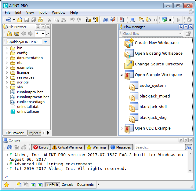
Figure 1. ALINT-PRO Initial View
The File Browser window and the Project Manager tab are shown on the left of the screen and the Flow Manager window is placed to the right, while Console stays at the bottom. This represents a default windows layout, which can be adjusted to the user's needs and saved for subsequent runs.
Creating Workspace and Project
The design needs to be organized as one or more ALINT-PRO projects, each representing an HDL library. Projects consist of design files (HDL sources, TCL scripts, etc.) and various preference settings that configure design entry and linting stages. Projects can logically represent a large isolated functional block of the design, or a re-usable IP-block, or a library of shared utility components.
ALINT-PRO workspaces represent a set of interdependent projects that altogether model the entire design. One of the member projects should be chosen as an Active Project. Elaboration, synthesis and constrain phases can only be executed for the Active Project, although it may reference design units from the other projects. The top-level unit must belong to the Active Project's library.
Using wizards to create new workspaces and projects
To create a new ALINT-PRO workspace, click the File menu, choose New, and then Workspace. The Create New Workspace wizard is opened.
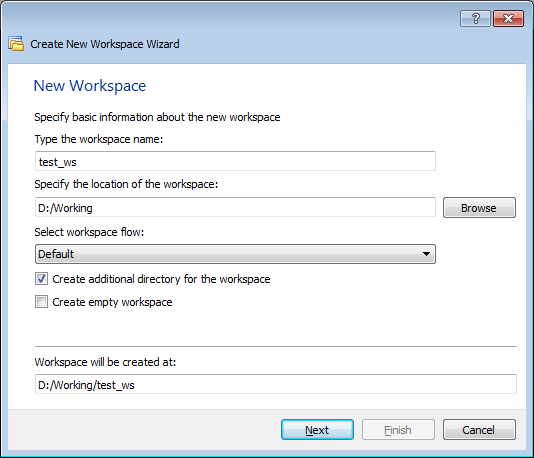
Figure 2. First Step of Create New Workspace Wizard
Workspaces need a name and a storage location, and one of the available workspace flows should be picked. The selected flow organizes the order of analysis into sub-phases to pursue specific goals and provides useful shortcuts for the most frequent use cases. Currently, it is possible to choose between:
Default - dedicated for phase-by-phase design entry and linting;
CDC - implements phase-based CDC debugging methodology.
You may optionally create an additional directory for the workspace and/or create an empty workspace (a workspace without any project). It's also possible to create a new sub-directory for the project.
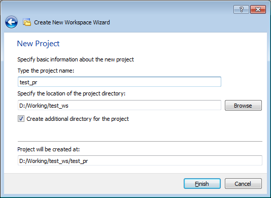
Figure 3. Optional Settings of Create New Workspace Wizard
If you create a new project without loading an existing workspace, ALINT-PRO automatically generates a new workspace with the identical name as the project. However, if a workspace is already open, then the new project is automatically attached to the current workspace.
The currently open workspace is shown within the Project Manager window. Changes to the structure of workspaces and projects are saved on disk automatically. Later you can open the existing workspace by selecting a corresponding *.alintws file on the disk.
You can also review the pre-installed example projects (except when the Minimal configuration was installed).
Creating Project from Disk Files
An alternative way to create a project is to pick a directory containing HDL sources in File Browser and run the Create Project command from the pop-up menu.
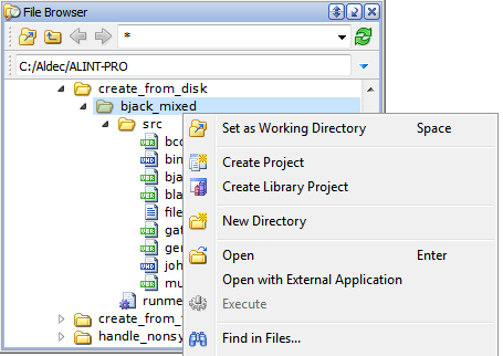
Figure 4. Creating Project from Disk Directory
The created project will include files from the selected directory and its subdirectories. The project will contain virtual folders mirroring the nested directory structure on the disk.
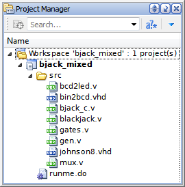
Figures 5. Created Project Structure
Adding Files
There are a few ways to create and add new files to an existing project:
Choose the File | New menu item, then click the icon representing the document type (e.g., VHDL File, Macro File, Text File, etc.); or
Click Add within the Project Manager pop-up menu, and select the New File option.
If you need to attach existing file(s) to the project:
Right-click the parent directory in File Browser, then choose Add to Project; or
Pick a workspace, a project, or a folder node in the Project Manager, click Add; then choose Existing File. A similar item called Files from List allows adding a set of files from the listing file, which is a frequent choice for ASIC designs, as well as for designs having automatic simulation or synthesis scripts.
Excluding Files from Analysis
Sometimes it might be necessary to disable processing of one or more design files, especially when adding the entire disk directories into the project. A canonical example is a supplementary Verilog file with shared `define directives, which is included into several modules and does not need to be treated as a regular source file. Another case is when the user has alternative versions of the same file (i.e., different constraint sets), and only one of them needs to be analyzed.
The Exclude File option of the file's pop-up menu excludes the selected HDL or constraints file from the analysis, but does not remove it from the project. This preserves the original project structure and allows including the file back into the processing using a similar Include File pop-up menu item. The excluded files are marked with an easily recognizable red cross icon.
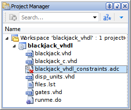
Figure 6. Excluded Constraints File
Projects Dependencies
Dependencies between the projects and files within the workspace affect the order of parsing: related projects are parsed before the projects that reference them. By default, ALINT-PRO does not assume any dependencies and only runs the specified project.
You can create and adjust the dependencies with the pop-up menu of the Project Manager window. Dependencies can be defined when the workspace is loaded. Select the project node and click the Dependencies item from the pop-up menu.
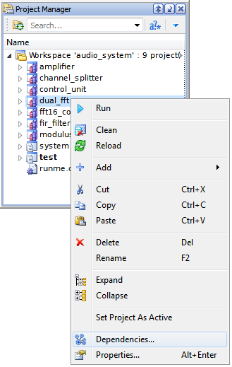
Figure 7. The Dependencies Pop-Up Menu Option
The Project Dependencies window provides access to the list of all the workspace's projects: choose the referencing project within the topmost drop-down list to select its dependencies. The next step is to select one or more dependent projects.
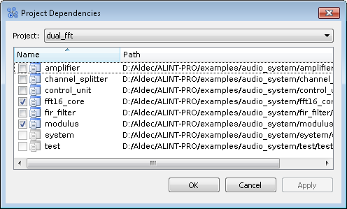
Figure 8. Setting dual_fft to be Dependent on Two Projects
Cyclic dependencies are forbidden, the Project Dependencies dialog will automatically disable the inaccessible options.
The dependencies between the files can be configured in a similar manner. File dependencies are mostly used to manually impact the parsing order within the containing project, which is useful in specific complex cases. However, normally this isn't required, and the obvious file-level dependencies, such as use of VHDL or SystemVerilog packages, instantiation of the design units, are extracted automatically. Manual dependencies are managed via the Dependencies pop-up menu item associated with the file nodes within Project Manager.
Global Preferences and Project/File Properties
Design entry and linting phases, as well as the reporting and debugging facilities in ALINT-PRO are highly configurable to match the particular needs of a concrete implementation technology and purpose of the project.
ALINT-PRO defines several levels of preference settings including Global Preferences, Project and File Properties. The most local settings take precedence over the settings specified for the wider context.
The global settings available in ALINT-PRO are accessible from the Tools | Preferences menu item.
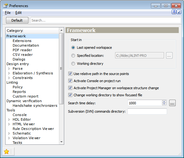
Figure 9. The Global Preferences Window
Newly created projects inherit the properties from the original global settings.
Project properties can be observed and modified via Properties of pop-up menu by right-clicking on the project node within the Project Manager window.
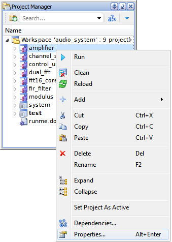
Figure 10. The Properties Pop-Up Menu Option
The Properties window has the following categories on the left side:
Design Entry;
Linting;
Dynamic verification.
To override the global settings, the user needs to clear the corresponding checkbox(es) in the rightmost top corner of the matching preference control. This makes the control editable. All the changes made in project Properties need to be manually confirmed by clicking the saving icon on the toolbar or by pressing Ctrl+S. The actual values are stored within the project's file (.alintproj) and are recovered after re-opening the project after ALINT-PRO restart.
One of the most important options is an exact LRM (Language Reference Manual) standard that should be used for parsing of source files. The Design Entry | Parse category offers special settings to select the version of VHDL, Verilog, and SystemVerilog standards.
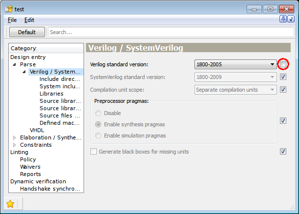
Figure 11. Setting Language Standard
Another important option is the list of libraries that should be searched for units instantiated in Verilog/SystemVerilog code. To use the units from a global or an attached library, specify the library at the Design Entry | Parse | Verilog/SystemVerilog | Libraries page. This step is especially important for FPGA designs, referencing pre-installed vendor-specific primitive components.
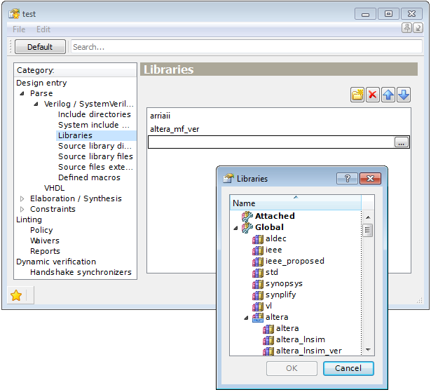
Figure 12. Library Specification
By default, a unit that is not instantiated within the design is automatically considered as "elaboration top-level". It becomes a root of the instance hierarchy tree. If a testbench unit is used in the design, then it is automatically detected as an "elaboration top-level". All units instantiated within a testbench are considered as "design top" units. Several key analysis procedures, such as detection of clocks and resets, DFT, and design partitioning rules will only consider the "design top" units and completely ignore the testbench parts. Including the testbenches into the ALINT-PRO analysis should generally be avoided, since the primary purpose of the tool is to check the synthesizable RTL parts of the design.
To specify the elaboration top-level unit manually, use the Design Entry | Elaboration / Synthesis | General | Top-level units page of the project Properties. There can be several top-level units in a project. Alternatively, top-level unit(s) can be set via the Library Viewer window (just use the Set as Top-level pop-up menu option for the pointed unit).
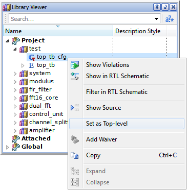
Figure 13. Setting top_tb_cfg as Top-Level
Values of generics/parameters can be externally redefined using the Design Entry | Elaboration / Synthesis | General | Generics page of the project Properties.
The limited number of preference settings can also be overridden at the level of individual source file. Right-click on the file's node within the Project Manager and select Properties item to open a similar configuration panel with a reduced number of pages. Whenever at least one property is altered for a given file compared to project-level properties, this file's node is highlighted with an exclamation mark within the Project Manager window.
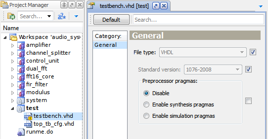
Figure 14. Modification of the testbench.vhd File Properties
Library
Libraries (.alintrepo files) store the content of design units after success of parse phase.
Library Viewer window demonstrates HDL libraries available for referencing within the currently open workspace. All the libraries are divided into Project, Attached and Global categories.
Double-clicking a certain design unit node within its containing library opens the HDL editor pointing to unit declaration in the original source file. Similar link is accessible via the Show Source pop-up menu item.
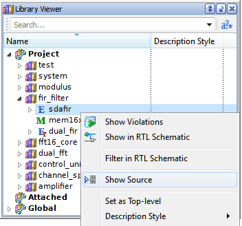
Figure 15. The Show Source Pop-Up Menu Option
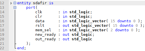
Figure 16. Cross-probing to the Source Code of Library Unit
ALINT-PRO distinguishes two types of libraries:
Project - automatically created (in .alint subdirectory) to store parse results of a project. It is a project's internal element and is being updated after each launch of parsing phase. When one or more files are removed from the project or if unit(s) is renamed/deleted from the HDL code, it is also removed from the library;
Exported - a detached copy of a project library, no longer dependent on project updates. This is useful for sharing a common library between several independent projects, i.e. a utility library or a 3rd-party IP block, which are rarely or almost never updated.
The project can reference design units from other projects that belong to the same workspace, assuming their parsing has already succeeded. One of the ways to share common HDL code parts between the different workspaces is to include the same project into those multiple workspaces.
The units that belong to an Exported library can be referenced by one of the projects when the library is Attached to the workspace.
Project and Attached libraries have local visibility - to the members of the containing workspace.
On the contrary, the Global libraries are automatically visible in any ALINT-PRO project. The mechanism of Global libraries enables access to standard VHDL libraries (std, ieee, vl), as well as to predefined sets of FPGA vendor libraries (Xilinx, Altera, Microsemi, Lattice, etc.). Links to all global libraries of particular ALINT-PRO installation are listed in the alint.libraries file located in the <install_dir>/vlib directory. The alint.libraries file is updated after any change to the set of global libraries.
Linting Policy
Every ALINT-PRO rule targets some commonly accepted design practice, a corporate style convention, or a popular method, which attempt to prevent some frequently occurring design mistakes. The exact set of what should be considered as "acceptable practices" may vary depending on the implementation technology, corporate culture and particular design decisions. The purpose of the Linting Policy mechanism is to allow user-defined configuration of the enforced implementation methods.
It is not a common practice to enable all 100% of provided rules simultaneously. Some of the rules are mutually exclusive, i.e. a typical FPGA-based project will require synchronous active-high resets, while an ASIC design will most probably expect an active-low asynchronous reset logic instead. A book on ASIC design might suggest clock gating as a method to reduce power consumption, however a direct use of the same RTL code in FPGA might lead to very poor timing properties.
A Policy represents a list of rules enabled for the analysis, as well as the values of provided rule configuration parameters. Policy is a re-usable valuable artifact that can represent the coding guidelines accepted within the organization for a certain class of designs.
Similarly, the linting policy can be configured globally or customized for individual projects.
Global policy enables rules from the predefined DEFAULT ruleset with the default values of configuration parameters. By default, the global policy affects all ALINT-PRO projects, unless they define their own policy. Use the Linting | Policy page of the global Preferences to modify the default settings.
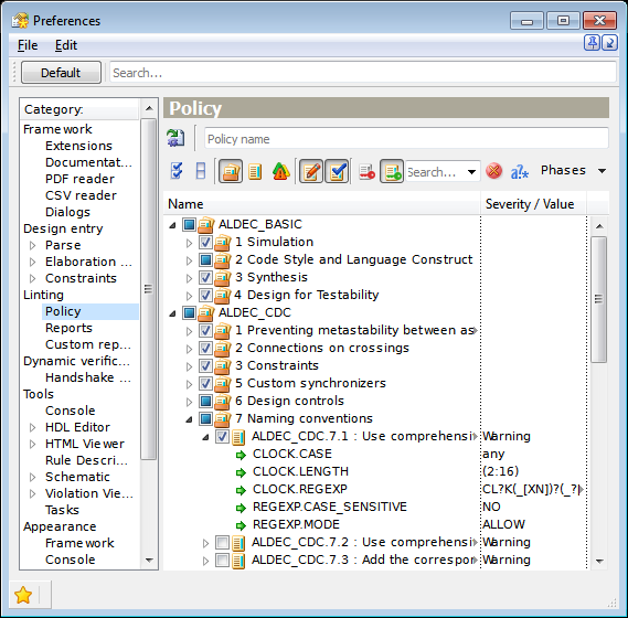
Figure 17. The Linting | Policy Page of the Global Preferences Window
Project-specific policy inherits the default values from the global policy, and allows further modification. The list of rules might be shortened or extended, and the parameter values can be modified. The Linting | Policy page of the project's properties will mark the modified rules compared to global policy to emphasize concrete changes.
Policies can be exported to a TCL macro for re-use in other projects. Simply running the same TCL macro in a different workspace re-creates the same policy in the new context.
For more detailed information refer to 'Customizing Linting Policy' Application Note.
Running Analysis
The order of design analysis phases can be managed in an organized manner using the Flow Manager window. It provides shortcuts for the most frequently executed steps. The flows have a hierarchical structure to cover basic and advanced user scenarios.
A particular flow can be selected during workspace creation, or modified later using the drop-down list in the Flow Manager's toolbar. The Default Flow is recommended as a basic template. Other flows, i.e. CDC Flow, target more specific verification goals.
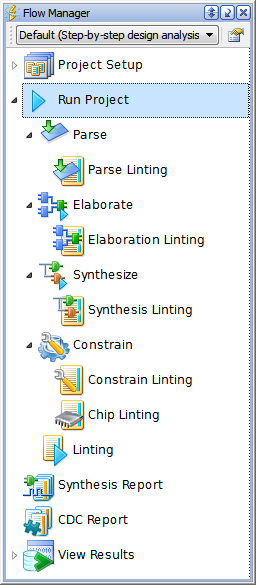
Figure 18. The Flow Manager Window
To run all the phases at once:
Click the Run Project node in the Flow Manager window;
On the main toolbar, click the Run button;
On the Project Manager window, point the project and click Run from the pop-up menu; or
Press F8.
Flow Manager displays the status of each executed phase. When a certain phase is currently running, Flow Manager displays an animated progress icon near the phase. If the phase succeeds, then a green status indicator is displayed. Similarly, if the phase fails, a red indicator is shown.
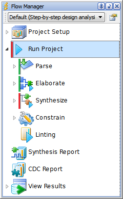
Figure 19. Phase Node Indication
Viewing Results
Results of each linting phase of the design verification can be viewed in the Violation Viewer window.
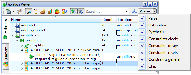
Figure 20. Drop-Down List of Linting Phases
Violations can be divided into groups according to their origin:
File - code formatting violations (indentation, alignment, comments, etc.);
Design unit - coding style violations (e.g., described constructs or naming conventions);
Elaboration unit - violations that take generic values into account (i.e., bit-width rules) and violations that require netlist for a single unit (i.e., flip-flop inference rules); and
Instance - chip level violations (control signals, design partitioning, CDC, DFT).
The results are shown in two tabs: Violations tab, which displays hierarchically organized origins with the violated rules and corresponding violations, and Summary tab presenting violation statistics.
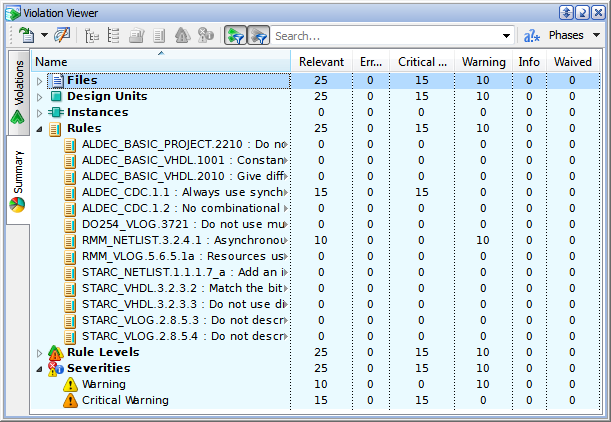
Figure 21. The Summary Tab of Violation Viewer
The Violation tab allows switching modes of violations organization (grouped by origins, rule names, etc.).
Violation Viewer provides right-click pop-up menu options to locate a violation in a source code, in a project structure, or in RTL scheme.
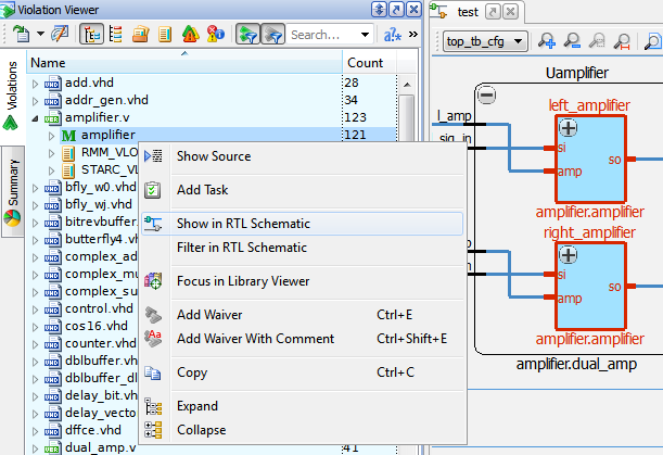
Figure 22. The Violation Viewer Pop-Up Menu
You can also use filtered search (via drop-down menu or search field) and sort violations by clicking the column headers.
Violation Reports
Violations detected during the design linting can be exported to files in different formats using the Violation Viewer toolbar buttons.
By default, a report file is named after the project and generally includes:
Execution information (ALINT-PRO version, project or workspace name, report generation date);
Summary part: violated rules structured by the projects or by certain criteria (e.g., violations origin, violated rule level, etc.) specified in Summary tab of Violation Viewer;
List of violations.
The summary part is only included if the option Include summary in violations reports is selected in the Tools | Violation Viewer page of the global Preferences.
The following report formats are provided:
Simple text report - sorted violations list. If the report is generated for the entire workspace, then the violations list is divided into parts corresponding to each project;
Full text report - sorted violations list in a tabular form with line number, design unit, instance, source, violation relevance, links to the HTML help articles about corresponding rules and source code fragments;
CSV report - sorted violations list separated by "," (by default). The separator symbol can be customized with Linting | Reports of the project Properties or global Preferences;
PDF report - list of violations sorted by rule title. Violation attributes (source file, line number, severity, violation relevance, etc.) are presented in a tabular form. This is the only report format that contains a filter section;
HTML report - provides a navigable design hierarchy, tabs for violations analysis, and cross-probing from violation messages to source files with syntax highlight. This report can be viewed in any modern HTML browser such as Chrome, Firefox, or within the built-in HTML browser.
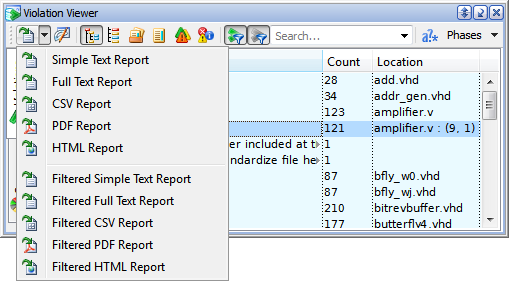
Figure 23. List of Available Report Formats
Conclusion
This application note introduced the design verification process using Aldec ALINT-PRO. It started from creation of a workspace, configuration settings, then went through the linting policy and flow runs, unto the reports generation.
For further reading, please refer to Application Notes 'Customizing Linting Policy' and 'Using Waivers to Skip Irrelevant Violations'.
Corporate Headquarters
2260 Corporate Circle
Henderson, NV 89074 USA
Tel: +1 702 990 4400
Fax: +1 702 990 4414
https://www.aldec.com
©2026 Aldec, Inc.