Phase-Based Linting Methodology
Introduction
This application note highlights the basics of Phase-Based Linting (PBL) methodology and explains how to use the Flow Manager to implement the methodology in your design checking and refinement process.
Traditional vs. Phase-Based Linting
ALINT provides two approaches to the design analysis and refinement process:
Traditional – all necessary rules (members of a current design checking policy) are applied at once. Traditional design rule checking applications analyze HDL designs against a set of hundreds of rules, leaving you to manage thousands of error and warning messages from a single linting session. In addition, the order of violations analysis is unknown hence the traditional approach is not efficient because of the design issue interdependencies.
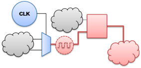
Figure 1: Example of Design Issues Interdependency
An example of design issue interdependency is given in Figure 1:
Violation #1: random logic is connected to a clock pin [the root issue].
Violation #2: complex clock domain issue(s) [redundant consequence].
The traditional approach does not provide any guidance therefore you may spend unnecessary time investigating complicated clock domain issues instead of quickly eliminating the root issue. The only benefit of the traditional approach is that it is very quick and easy to set up and use.
Phase-Based Linting (PBL) – the design is refined by following a step-by-step set-up process. This approach requires some investment in time upfront over the traditional approach, but it provides valuable return long term and more importantly, can be reused across multiple projects.
The major advantage of using PBL is minimized number of design refinement iterations and clear focus on certain type of design issues at every stage. The methodology allows for the incremental process of design analysis and refinement and eliminates the problem of design issue interdependencies. PBL is much faster compared to the traditional debugging method – it speeds up debugging time by 3—10X! This is true for relatively large designs since the amount of interdependencies grows exponentially with a design size.
If you resolve the issues in the right order then the total number of rule violations to deal with becomes significantly lower. If you consider the basic rules first and solve a problem then it will not trigger any other violations. This becomes especially critical as you get to the more advanced design rules that require more effort to analyze and fix.
Linting Flow Manager
The Phase-Based Linting methodology is implemented based on the Linting Flow Manager. The linting flow is a process or set of phases that must be executed and completed sequentially. Every phase addresses a certain set of design issues and may also have the “pass criteria” (quality requirements that should be satisfied until the next stage becomes available). The information about every linting flow is stored in a separate .alintflow file – such a file can be attached to any design using the Flow Manager.
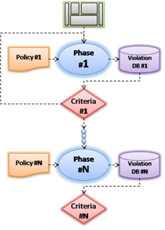
Figure 2: Phase-Based Linting
As you can see in Figure 2, every phase must satisfy certain quality requirements before the next phase becomes available. There are two types of configurable criteria (exclusively or combined):
Design Quality at current phase – integral number which is calculated based on the ratio of violated and non-violated rule weights.
Critical rules that must not be violated – selection from the rules set that is used at current phase.
And there are two types of phase in every linting flow – regular and optional. A linting flow cannot be completed until quality requirements (regular) are satisfied; optional stages are not required for flow completion.
A sample linting flow is shown in Figure 3:
Any particular phase can be executed by double-clicking its name. If there are any previous phases that were not completed they will automatically execute first to prevent the regressions. However, for simplicity, the Flow Manager has the Run button that runs step-by-step execution of the complete flow.
Sample flow has 3 phases: “Phase 1 – Basic”, “Phase 2 – Intermediate”, “Phase 3 – Advanced”.
The execution process is stopped at the “Phase 1 – Basic” phase because of the critical rules violation.
Quality and critical rules columns reflect the current quality status (green when good enough).
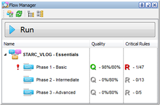
Figure 3: Linting Flow Sample
The red exclamation mark in front of the “Phase 1 – Basic” phase (Figure 3) indicates that it was not completed. Here is the list of all possible statuses:
 Regular phase is completed successfully – pass criteria are satisfied and next phase is available.
 Regular phase is completed – but pass criteria are not satisfied.
 Optional phase is completed – but pass criteria are not satisfied.
 Phase has been changed after its previous execution – should be executed again.
 Phase execution has failed due to an error (e.g. syntax mistake in the analyzed HDL code).
And here are the corresponding states for pass criteria indicators:

 Phase execution completed – pass criteria satisfied.

 Phase execution completed – pass criteria not satisfied.

 Phase was not executed.

 Phase was executed – pass criteria status unknown (execution failed, properties changed, etc).
Please note that stage (and complete flow) execution results are also indicated in the Console – sample report is shown in Figure 4.
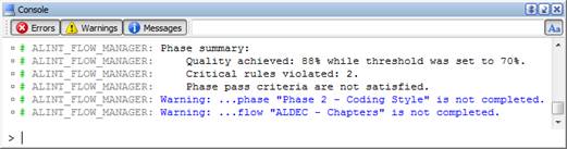
Figure 4: Sample Flow Execution Results in the Console
Each phase execution results are stored in a separate Violation Database (.avdb). Right-click on any phase and select the View Phase Results menu item to analyze the violations that were detected during that phase execution. A dedicated Violation Viewer is available for convenient violations analysis (all the standard features are included – cross-probing, filtering, export to different formats, context-dependent reference, exclusions engine, and many more). Note that critical rule violations are highlighted red.
Attaching Flow to a Design
There are three options available if you want to attach a linting flow to your design:
Create custom linting flow manually using the dedicated Flow Wizard. The advantage of this method is that it is fully customizable although it may take some time to setup and organize the rule phases.
Use one of the predefined templates that are shipped with the product. These templates were developed by Aldec experts and are highly optimized. You may want to review the contents of each phase to ensure that the rules are relevant to your project.
Use one of the predefined classifications that are shipped with the product. These classifications include rules grouped by various topics, as though they would appear in a design guideline. You can use them to quickly pick up those areas that you want to cover. Please note however that it is your responsibility to minimize the interdependencies when you use the classification-based flows.
In order to attach a flow to your design, select the File | New | Flow menu item – the new flow creation wizard (as shown in Figure 5) will appear.
And you have to make the decision here whether you want to create a custom flow manually or use a predefined flow template or classification (i.e. do this automatically). These options are controlled by the Based on Predefined Template and Based on Classification checkboxes. We recommend predefined flow templates to all new users because they allow to jumpstart the process of design analysis and refinement without spending significant amounts of time on customization.
The set of predefined flows depends on the installed rule plug-ins – i.e. the following templates are available if only the basic rule library is installed:
“ALDEC – Chapters” for mixed language (Verilog and VHDL) design.
“ALDEC_VHDL – Chapters” for VHDL only designs.
“ALDEC_VLOG – Chapters” for Verilog only designs.
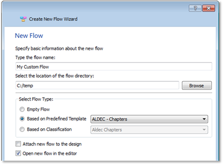
Figure 5: Custom Flow Creation Wizard
After a flow is attached, its name appears next to the design name in the Design Manager (see Figure 6), and the flow becomes ready for use – the flow content is loaded into the Flow Manager.
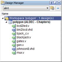
Figure 6: The “Aldec – Chapters” flow is attached to the “polygon” design
And now you just have to complete the step-by-step process:
Click the Run button in the Flow Manager to execute the current flow.
Wait until flow execution stops at a stage that requires your attention (if any).
Fix any violations detected at this stage and go to the 1st item on this list.
Please note that it does not matter whether a flow was created from a template or manually – it can be customized depending on your specific project needs. Use the Flow Editor tool (Figure 7) to manage and customize your flows.
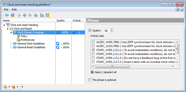
Figure 7: Flow Editor (Basic Phase Settings View)
The Flow Editor tool has two main working areas, flow structure on the left and context-dependent settings pane on the right. The settings pane depends on a node that is currently selected in the flow structure and allows managing your flow settings on-the-fly; the list of available actions is explained in Table 1.
Table 1: Flow Editor Functionality Description
Node Selected in the Flow Management Tree |
Actions Available at the Context-Dependent Pane |
Phase |
Customize basic settings of a currently selected phase:
|
Policy |
Manage policy contents and configure its rules using the built-in Policy Editor and Parameter Editor. |
Preferences |
Customize additional preferences of a relevant phase:
|
The flow structure can be managed using the Main Toolbar or dropdown menu. Completing the wizard to create a custom phase allows you to add, remove, rename, and arrange the order of flow phases easily. Phases can also be grouped in a hierarchical manner using the Group Nodes. This allows you to achieve fine-grained control over the flow by having fewer rules to check per phase and grouping them by particular technology aspects.
PBL Use Case
We have compared the traditional and Phase-Based Linting methodologies on a very simple design. The predefined “STARC_VLOG – Essentials” was used and all violations were fixed during every phase. STARC® (Semiconductor Technology Academic Research Center) is consortium of major Japanese ASIC foundries that has established the set of design guidelines based on industry-proven design practices.
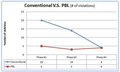
Figure 8: Use Case - PBL Compared to Traditional Methodology
The results of this comparison are displayed in Figure 8:
The red curve represents the number of design issues that were detected with PBL Methodology at every stage of the “STARC_VLOG – Essentials” flow.
The blue curve represents the number of violations that would have appeared with the traditional approach (i.e. the entire STARC policy at once) even being given completely correct order of analysis with all interdependencies taken into account.
Summary
The Phase-Based Linting methodology puts clear priorities into the design analysis process by reducing the total number of issues to deal with and minimizing the number of design refinement iterations. It speeds up debugging time by 3—10X compared to the traditional approach.
The key features in Phase-Based Linting (PBL) in ALINT:
The Phase-Based Linting Methodology is implemented based on the Linting Flows.
Linting Flow is a process – a set of phases that must be executed and completed sequentially.
Every phase has its own set of rules and the pass criteria (quality requirements).
Phases can be regular or optional and each of them typically addresses certain type of issues.
Flows are stored in .alintflow files that can be attached to designs.
Attached flow name appears next to design name and can be executed via the Flow Manager.
Predefined flow templates are optimized and ready to use out-of-the-box.
As well as the predefined flows, you can create a custom flow and reuse it across projects.
Flow Editor is a dedicated tool for custom flows management.
Applies To:
ALINT 2012 Windows
ALINT 2012 Linux
Corporate Headquarters
2260 Corporate Circle
Henderson, NV 89074 USA
Tel: +1 702 990 4400
Fax: +1 702 990 4414
https://www.aldec.com
©2026 Aldec, Inc.