How to Simulate Designs in Active-HDL
Introduction
This chapter describes how to stimulate input signals in the Active-HDL simulator. Active-HDL supports the following methods of stimulating or forcing input signals during the simulation:
Manually selected stimulators from the Active-HDL resources
VHDL or Verilog TestBench files that have been created by the TestBench Wizard
User created VHDL or Verilog TestBench files
VHDL WAVES TestBench files (as per IEEE WAVES specification 1029.1)
Verilog Result Comparison TestBench files
Simulation commands entered from the console window
Files containing simulation macro commands
Simulation input based on waveforms edited by the user
All these methods providing design stimuli can be combined in the same design. You can choose a method which is best suited for your specific design needs and be confident that a good balance between the time required to create simulation input and the complexity of the design verification exist.
Stimulators
The easiest way to create simulation stimuli is by adding the desired signals to the Waveform Editor and assigning stimulators that are available from the Stimulators option. There are several options to choose from. The following stimulator types are supported:
Clock Stimulator
Typically, the Clock stimulator is used to drive clock signals. This type of the stimulator also can be applied by using the -repeat <period> argument of the force macro command. The Clock stimulator produces a rectangular wave defined by the following parameters:
frequency / period
initial offset time
duty cycle
initial value
Counter Stimulator
The Counter stimulator can be applied to VHDL signals of one-dimensional array types and integer types and Verilog integer registers and vectors. It produces a sequence of values that represent consecutive states of a counter. You can set the count step and direction, the time interval between consecutive counts, the initial value of the counter, and the counter type (Binary, Gray, Johnson, Circular One, and Circular Zero).
Custom Stimulator (Standard Waveform Viewer/Editor)
The Custom stimulator forces a signal or net with its own waveform (the waveform must already exist in the Standard Waveform Editor window before simulation). You can create the waveform manually by using editing features of the Waveform Editor. More typically, you will re-use a waveform obtained in the previous simulation run or loaded from a waveform file. Consider the following example: during the simulation, you were using a Hotkey stimulator to create a waveform on a certain signal. To re-use so created waveform during subsequent simulation runs, you should change the type of the stimulator from Hotkey to Custom after the re-initialization of the simulation.
Formula Stimulator
The Formula stimulator produces a waveform defined by an expression based on a pre-defined syntax. The waveform is defined as a sequence of value-time pairs. The time argument determines the moment the stimulated signal assumes the value defined by the value parameter. In addition, a formula can include the -repeat <period> argument which cause that the sequence is repeated with the specified period.
The syntax of formulas is as follows:
<value <time> [ , <value> <time> ... ] [ -r <period> ]>
Hotkey Stimulator
A Hotkey stimulator is similar in concept to a value stimulator but it provides a convenient mechanism for changing the forced value. To change the stimulator value, you have to simply press a specific key. Pressing the key usually toggles between two signal values, for example, '0' and '1'. However, you can define a longer list of values that will be sequentially switched by the hotkey.
Predefined Stimulator
A Predefined stimulator is either a clock- or formula-based stimulator to which a unique name has been assigned. Since the stimulator can be referenced by its name, you can easily assign it to several signals without repeating its definition each time.
Random Stimulator
The Random stimulator is based on the random numbers generator. It returns integer values distributed according to standard probabilistic functions. The following functions of distribution are available:
Chi-square
Erlang
Exponential
Normal
Poisson
Random
T
Uniform
Value Stimulator
A Value stimulator drives the signal with a constant value. If you advance simulation step by step, you can change the value between steps by redefining the stimulator. This type of the stimulator also can be applied by using the force macro command.
Advantages of Stimulators
The quickest and easiest method of forcing signals to the desired states.
Interactive assignment of stimulators allows instant viewing of the simulator's response.
Stimulators can be applied to any signal and port in the design hierarchy.
Handy in debugging low level processes and architectures.
Disadvantages of Stimulators
VHDL or Verilog TestBench can only drive signals at the top design level.
Stimulators are saved as waveform files.
Stimulators are not sufficient for performing such complex simulations as reading data files, etc.
Stimulators are proprietary to Active-HDL and will not work in other HDLs simulators.
Waveform Editor
The Waveform Editor allows you to graphically edit any waveform by using dragging, copying, pasting and drawing new waveform signals. These waveforms can be used as custom stimulators by assigning them to the desired signals. Graphically edited waveforms can also be used as simulation input in conjunction with the TestBench Wizard, described later in this document, which generates a VHDL or Verilog test program that is based on the edited waveforms.
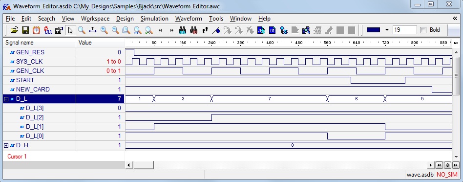
Figure 1. Sample Simulation Run
Comparison of Simulation Results
Waveform Editor also allows comparison of the simulation results. Signals for which the difference was
detected are displayed in the Waveform Editor window with the red color. The icon  enabling the comparison of
signals is located in the upper part of the window. The previous simulation run results must be first saved in
the project folder. In case of indifferences in simulation runs an appropriate message is displayed.
enabling the comparison of
signals is located in the upper part of the window. The previous simulation run results must be first saved in
the project folder. In case of indifferences in simulation runs an appropriate message is displayed.
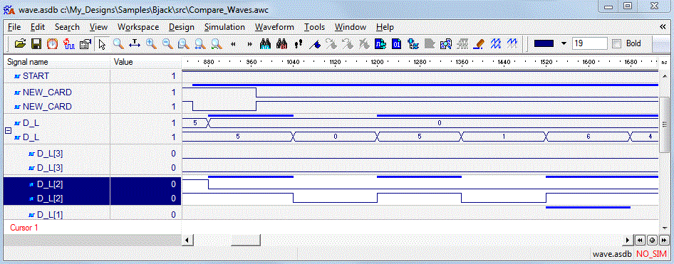
Figure 2. Comparing simulation runs
Simulation Macros
Macros Entered in the Console Window
Active-HDL provides a macro command language for manually entering simulation commands, such as forcing signal values, assigning formulas and executing simulation steps. You can force a value on a signal at any time during simulation by entering the appropriate macro commands in the Console window. You can also use macro commands to add forced signals to the Waveform Editor, etc.
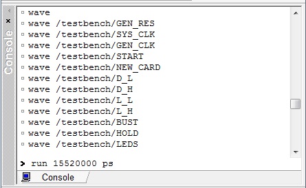
Figure 3. The Console window
Example:
Wave - creates an empty waveform
Wave CE - adds CE signal to waveform
Wave RESET - adds RESET signal to waveform
Wave LOAD - adds LOAD signal to waveform
Wave DIN - adds DIN signal to waveform
Wave DIR - adds DIR signal to waveform
Force LOAD 1 0ns, 0 10ns - changes LOAD to 1 at 0ns and to 0 at 10ns
Force CE 1 - changes CE to 1
Files Containing Macros
The simulation macro commands can be executed from a file, saving you time on the manual entry of every command in the Console window. Simulation macros not only can force input signals but they can also execute other commands in the Active-HDL environment. This allows complete automation of the design verification process, particularly when combined with other simulation entry methods. For example, you can write a script to run a number of simulations using several TestBench files, one after another. Macro scripts can execute external programs such as a synthesis program, batch files, etc. You can also invoke custom commands developed in Script Basic, which are included with Active-HDL, for automation purposes.
Advantages of Macro commands
Fast stimulator entry, directly from keyboard.
No need to use GUI windows.
Familiar to Model Technology simulator users.
Allows automation of the entire simulation process.
Disadvantages of Macro Commands
Proprietary format of the simulation commands.
Requires knowledge of the macro language commands.
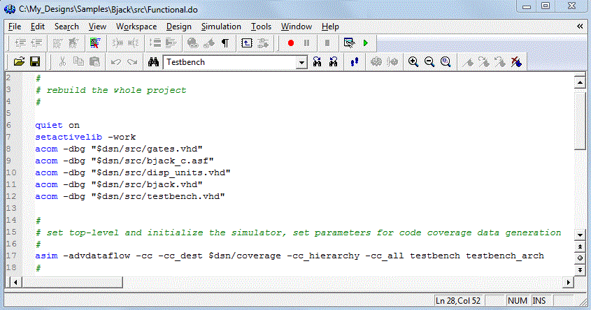
Figure 4. The Macro Command File
HDL TestBench
The HDL TestBench is a VHDL or Verilog program that describes simulation inputs in standard HDL language. There are a variety of VHDL or Verilog specific functions and language constructs designed to create simulation inputs. You can read the simulation data from a text file, create separate processes driving input ports, and more. The typical way to create a TestBench is to create an additional VHDL or Verilog file for the design that treats your actual VHDL or Verilog design as a component (Unit Under Test) and assigns specific values to this component input ports.

Figure 5. Testbench
The TestBench Model
The HDL TestBench can provide simulation inputs and also test the design outputs. For example, you can create a VHDL or Verilog program that writes design outputs to a text file and compares it against a reference file having the expected values. This methodology provides the most robust design verification with minimum user interaction.
TestBench Created with the TestBench Wizard
Creating TestBenches is a tedious process. The TestBench wizard automates this process by guiding you through the process. First, it asks you to select the top level design entity to be tested. Next, you need to enter the name of the waveform file with the desired input and output ports. After answering a few additional questions, the TestBench wizard gathers the necessary information and creates a template for the test program. You can edit the wizard-generated file; adding your own test scenario and additional inputs, if required.
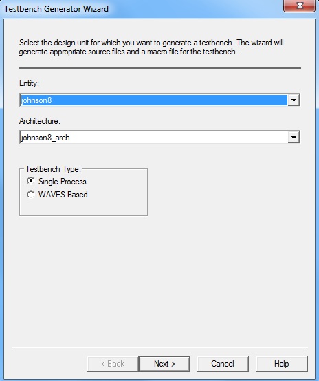
Figure 6. TestBench Wizard (VHDL)
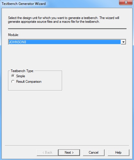
Figure 7. TestBench Wizard (Verilog)
Example:
module TOP;
reg CLK;
reg RES;
wire [3:0] Q_UUT, Q_REF, Q_V;
reg COMP_RES;
integer file;
//Component declaration of the tested unit
counter1 UUT (.CLK(CLK), .RES(RES), .Q(Q_UUT));
endmodule
VHDL TestBench in IEEE WAVES Format
The TestBench wizard allows you to create a template compliant with the IEEE WAVES 1029.1 specification. WAVES is a specification for creating TestBench files in the VHDL language. It describes simulation inputs with a specific language implemented as a set of VHDL libraries. It supports verification and testing of hardware designs at any level of abstraction. You do not have to be familiar with the WAVES specification to create these files. If you select this option, the TestBench Wizard will automatically format your TestBench program using the WAVES specification. The main benefit of using this format is the ability to format simulation input and output files so that they can be used interchangeably between various simulators. The WAVES format also contains some very useful high level functions for comparing simulation outputs without writing a lot of VHDL code. The standard TestBench functions are provided in a compiled WAVES library and allow reading and writing of TestBench files in the WAVES format.
The difference between the WAVES TestBench and other TestBench files are:
It provides a standard file format for waveform data, including formula expressions and stimulator types
It has some very useful high level functions for typical TestBench operations
HDL TestBench Created by the User
The VHDL or Verilog TestBench that you create will be treated as one of the VHDL or Verilog files in the design. You can import existing TestBench files and create the new ones from scratch. There are some VHDL packages provided in Active-HDL that include TestBench functions. The Language Assistant provides some examples of using simulation specific VHDL and Verilog constructs. For more information about writing your own simulation TestBench please refer to the VHDL and Verilog literature. Some of the more useful titles are listed at the end of this document.
Advantages of TestBenches
This advanced-code simulation input has powerful capabilities
It's non-proprietary format allows you to run the same simulation on any HDL simulator.
TestBench can provide simulation inputs and check design outputs at all design stages.
Disadvantage of Testbeches
Writing TestBenches is a time consuming process, particularly during the initial design verification.
Writing a TestBench requires good VHDL or Verilog knowledge
Example:
#Read cycle for rams with memfiles
IF (MEMFILE)
THEN FOR i IN 0 TO number_of_iterations LOOP
a_bus <= conv_std_logic_vector(i, addr_width); wr_en_pin <= '0';
clock_low(wr_clk_pin);
spo_bus_exp := conv_std_logic_vector(
conv_integer(a_bus)MOD(2**bus_width),bus_width);
clock_high(wr_clk_pin);
FOR k IN 0 TO bus_width-1 LOOP
IF (spo_bus_exp(k) /= spo_bus_behv(k)) THEN
ASSERT FALSE
REPORT (ERROR: Wrong output while reading mem file.)
SEVERITY ERROR;
exit;
END IF;
END LOOP;
END LOOP;
END IF;
Conclusion
As demonstrated in this chapter, Active-HDL provides a variety of methodologies for stimulating designs. For optimal results, use the most appropriate type of stimulator for each design stage. In the beginning of the design cycle you may want to use interactive stimulators to quickly create simulation inputs and view the design responses instantly. As you develop a better plan for testing your design, you may want to convert the stimulators to a VHDL or Verilog TestBench using the TestBench wizard. You can add to it any additional VHDL or Verilog test functions you may desire. At the end you can add some simulation scripts to automate the verification process and invoke your TestBench in the batch mode along with other design tasks such as synthesis, implementation and for the comparison of results from different design stages. For more detailed information how to create simulation inputs, please refer to the on-line documentation in Active-HDL.
Corporate Headquarters
2260 Corporate Circle
Henderson, NV 89074 USA
Tel: +1 702 990 4400
Fax: +1 702 990 4414
https://www.aldec.com
©2026 Aldec, Inc.