Getting Started with Active-HDL
Introduction
This tutorial provides instructions for using the basic features of the Active-HDL simulator. Active-HDL is an integrated environment designed for development and verification of VHDL, Verilog, System Verilog, EDIF, and System C based designs. In this tutorial we use a sample VHDL design called PressController from the Active-HDL installation to perform design entry and simulation.
Getting Started
You will first need to install latest version of Active-HDL on your computer to be able to successfully complete this tutorial. It is available as a free download from http://www.aldec.com/Products.
Creating Workspace and Design
In Active-HDL, individual designs along with their resources (source files, output files with simulation results, etc) can be grouped together as a workspace. The workspace allows adding and working with several designs simultaneously
Go to menu File | New and click Workspace. The New Workspace Wizard starts.
Type the workspace name and select the location where you want to create the project (you can use the Browse button to locate the folder).
NOTE: If you check the Create new design option, the New Workspace Wizard will be followed by the New Design Wizard. This way you can create a new workspace and a new design (attached to the workspace) in the same time.
Click the OK button when you are done (see Figure 1).
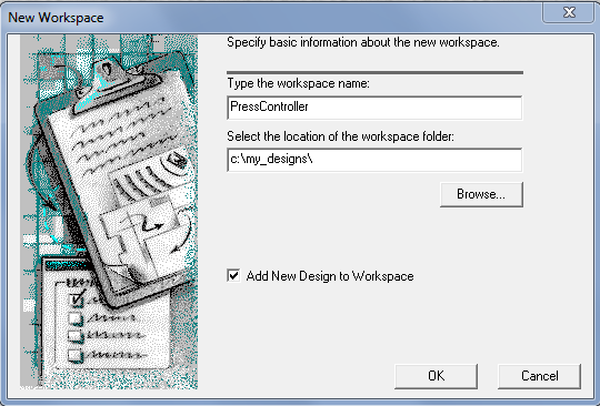
Figure 1 Create new workspace Wizard (Workspace Window)
A window will pop up for creating new design (see Figure 2).
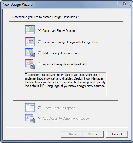
Figure 2 Create new workspace Wizard (Design Window)
Choose the Design Language i.e. Block Diagram Configuration and Default HDL Language (in our case VHDL). Then specify the Target Technology if you have any e.g. Vendor and Technology.
Specify the design name and select the location of design folder (exact same as the workspace). The name of the default working library of the design is same as the design name (see figure 3).
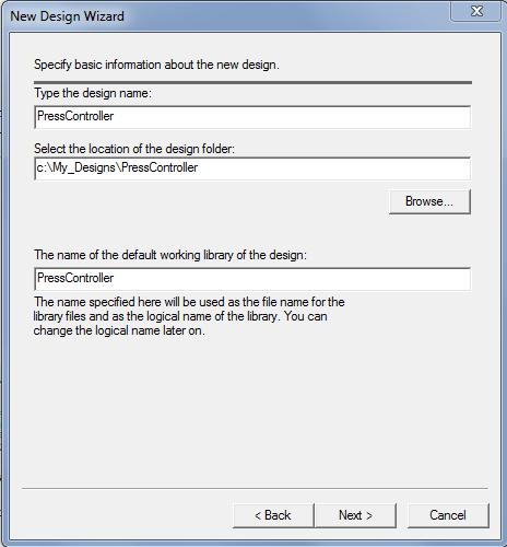
Figure 3 New Design Wizard
Click the FINISH button when you are done.
The Design Browser now shows a workspace name and new design attached with it (see Figure 4).
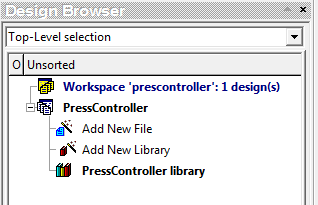
Figure 4 Design Browser after creation of workspace and design
Creating/Adding Files to design
To create a new file or an existing file or to create a directory, right click the Add New File option and then the desired operation.
You can also use File | New menu to open new files and save it to design directory (see Figure 5).
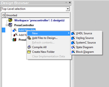
Figure 5 Adding Files to the Workspace
Creating HDL Source Code
If you want to create VHDL/Verilog/System C Source file, double-click the Add New File option and choose the correct source file type. A new editor window will open on the right hand side of the Design Browser. Text-based design entry will look like Figure 6.
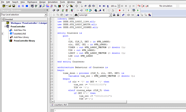
Figure 6 Creating a VHDL Code File
Creating a new State Diagram in State Diagram Editor
Double click the Add New File in the Design Browser. Select State Diagram and specify the name of the file.
Ports, signals, states and transition can be added with the help of the FSM menu.
Adding Ports to diagram
Choose Port | Input/ Output/ Bidirectional Port from the FSM menu.
Move the mouse pointer to the top of the diagram sheet (above the machine frame) and click where you want to place the port.
The port has a default name assigned. To change the name, click the port symbol with the right mouse button and choose Properties from the shortcut menu. Next, change the name in the Port Properties dialog and click OK.
Adding signals or variables to the diagram
Choose Signal/Variable from the FSM menu.
To define a variable, move the mouse pointer inside the machine frame and click where you want to place the signal/variable symbol.
To define an internal signal, move the mouse pointer to the top of the diagram sheet (above the machine frame) and click where you want to place the signal/variable symbol.
The variable or signal has a default name assigned. To change the name, click the symbol with the right mouse button and choose Properties from the shortcut menu. Next, change the name in the Properties dialog and click OK.
Adding States to the Diagram
Choose State from the FSM menu. The mouse pointer will adopt a new shape.
Move the mouse pointer inside the machine frame and click where you want to place the state.
The state has a default name assigned. To change the name, click the state bubble with the right mouse button and choose Properties from the shortcut menu. Next, change the name in the State Properties dialog and click OK.
Choose Action | State from the FSM menu for assigning state action. Move the mouse pointer so as to place its dotted end within a state bubble and click to anchor it. An edit box will appear. Enter the action statements and click anywhere within the diagram to close the edit box.
Choose Action | Entry from the FSM menu for assigning entry action. Move the mouse pointer so as to place its dotted end within a state bubble and click to anchor it. An edit box will appear. Enter the action statements and click anywhere within the diagram to close the edit box.
Drawing Transitions between states
Choose Transition from the FSM menu. The mouse pointer will adopt a new shape.
Click within the state bubble in which the transition begins.
Click within the state bubble in which the transition ends. The transition line will appear and the mouse pointer will adopt the normal selection shape.
To reshape the transition arrow, drag the small rectangular markers visible on the transition arrow or drag the middle part of the arrow.
Click anywhere within the diagram to deselect the transition arrow. The markers will disappear.
Choose the Condition from the FSM menu for assigning transition conditions.
After adding everything explained above, your State Diagram will look like Figure 7.
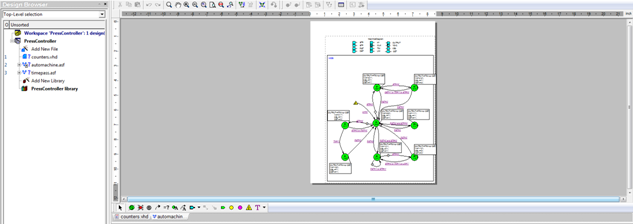
Figure 7 State Diagram
Creating a new Block Diagram in Block Diagram Editor
Double click the Add New File in the Design Browser. Select Block Diagram and specify the name of the file.
Symbols, wires and buses, FUBs (Functional Unit Block), HDL statement with the help of the BDE menu.
Adding Symbols in Block Diagram
Open the Symbol Toolbox from the View menu. Drag the symbols from the Symbol Toolbox and place it on the diagram.
Click with the right-mouse button over the Symbol Toolbox window and choose Select Libraries from the shortcut menu. The contents of the Symbols Toolbox window will be updated immediately.
Adding New Wires
There are two methods of drawing wires. The first method is based on consecutive clicks and the other requires that you hold the mouse button while drawing.
Go to the Diagram menu click on the Wire.
Click where you want start drawing the wire.
Move the mouse pointer toward the point where you want to end the wire. When moving the mouse pointer, a temporary wire line will be stretched between the wire origin and the current location of the mouse pointer. If you want to anchor a corner on the wire being drawn, click with the mouse button.
Click where you want to end the wire. If you want to end the wire in empty diagram space, you must double-click instead of the single click.
To draw another wire, repeat steps 2 to 4.
To draw a new wire using the method with the pressed-in mouse button
Go to the Diagram menu click on the Wire.
Move the mouse pointer to the point where you want to start drawing the wire, and then hold down the mouse button.
While holding the mouse button, move the mouse pointer toward the point where you want to end the wire. When you move the mouse pointer, a temporary wire line will be stretched between the wire origin and the current location of the mouse pointer. To anchor a corner on the wire being drawn, press Space while still holding the mouse button.
Release the mouse button to end the wire.
To draw another wire, repeat steps 2 to 4.
Adding New Buses
Drawing new bus is similar to drawing new wire. You have to select Bus instead of Wire from the Diagram menu and repeat steps 2 to 4 of Adding New Wires.
Adding New FUB
Adding a new FUB (Functional Unit Block) is also similar to drawing new wire. You have to select FUB instead of Wire form Diagram menu and repeat steps 2 to 4 of Adding new wires.
After adding everything, your Block Diagram will look like Figure 8.
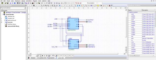
Figure 8 Block Diagram
Generating Testbench
The Testbench Wizard is designed for automatic generation of testbench files (one macro file and a number of source files) based on the user-defined specification. One of the most important information entered by the user is the test vector file name. A testbench generates stimulus for the UUT entity on the basis of test vectors defined in this file.
The Testbench Wizard accepts the following file types:
Standard Waveform Viewer/Editor (*.awf) or Accelerated Waveform Viewer (*.asdb) files.
WAVES-compliant test vectors files (*.vec).
VHDL and Verilog source files with pieces of code producing desired waveforms (*.vhs, *.ver, *.vhr).
For generating a Testbench:
Select Generate Testbench from the Tools menu.
Or from the File tab in the Design Browser, expand the branch showing the contents of the default working library or source file (HDL, block or state diagram file). Right-click the entity-architecture pair, module, or cell for which you want to generate a testbench, and then select Generate Testbench from the shortcut menu.
Compilation
Compilation is a process of analysis of a source file. Analyzed design units contained within the file are placed into the working library in a format understandable to the simulator. In Active-HDL, a source file can be VHDL file/ Verilog file/ EDIF netlist file/ State diagram file/ Block diagram file.
In case of a block or state diagram file, the compiler analyzes the intermediate VHDL, Verilog, and EDIF file containing HDL code (or netlist) generated from the diagram ($dsn\compile). Active-HDL provides three compilers, respectively for VHDL, Verilog, and EDIF. When you choose a menu command or toolbar button for compilation, Active-HDL automatically employs the compiler appropriate for the type of the source file being compiled.
Compiling Files
If you want to compile a single file, go to the Files tab in the Design Browser, right-click the file, and choose compile from the shortcut menu.
If you choose Compile All from the Design menu for a given design, the compiler automatically reorders the source files to ensure proper sequence in which design units are compiled (see Figure 9).
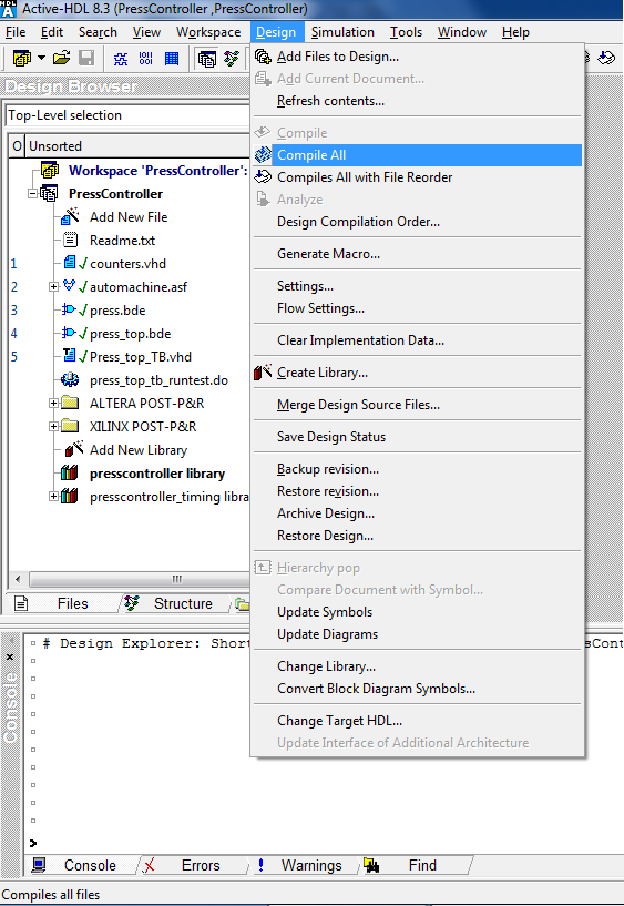
Figure 9 Compiling the Files
If you choose Compile All with File Reorder from the Design menu, only VHDL files (including Block and state diagram files targeted to VHDL) undergo reordering. Other source files (Verilog and EDIF) are ignored.
NOTES:
All messages (infos, warnings and errors) generated during compilation are displayed in the Console window or if enabled, on the Compilation tab.
Library units resulting from the compilation of a source file are placed into the working library selected for this file. By default, all source files in the design will be compiled into the default working library.
Initializing the Simulation
Once all needed design units have been successfully compiled, you can initialize simulation. Before you initialize simulation, make sure that:
You have selected the top-level design unit. You can select the top level in three ways:
Select the desired VHDL design entity or configuration, Verilog module, EDIF cell, or SystemC module from the drop-down list located at the very top of the Design Browser window.
Expand a structure of a source file (containing a top-level unit) or current working library in the Files tab, right-click the desired design unit and then choose Set as Top-Level from the shortcut menu.
Open the Design Setting Window. By default, the General category is displayed. Go to the Top-level category and select a top-level unit from the list of design units.
You have set the desired value of simulation resolution. For this go to Settings from the Design menu. The Design Settings dialog box will open. On the Simulation category, choose either the desire simulation resolution value or Auto. Click OK to close the dialog and complete the operation (see Figure 10).
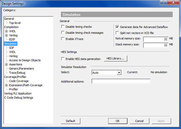
Figure 10 Simulation Resolution Setting
If you run the simulator without any top-level unit selected, Active-HDL will prompt you with a dialog box to select one.
To begin simulation, you must choose Initialize Simulation from the Simulation menu. The command launches elaboration and initialization of the simulation model. During elaboration, the simulator loads design units and builds the simulation model in the computer memory. During the initialization, all objects in the model (signals, variables, etc.) acquire their initial values (either default or explicitly specified) and all concurrent processes are executed once until their suspension (see Figure 11).
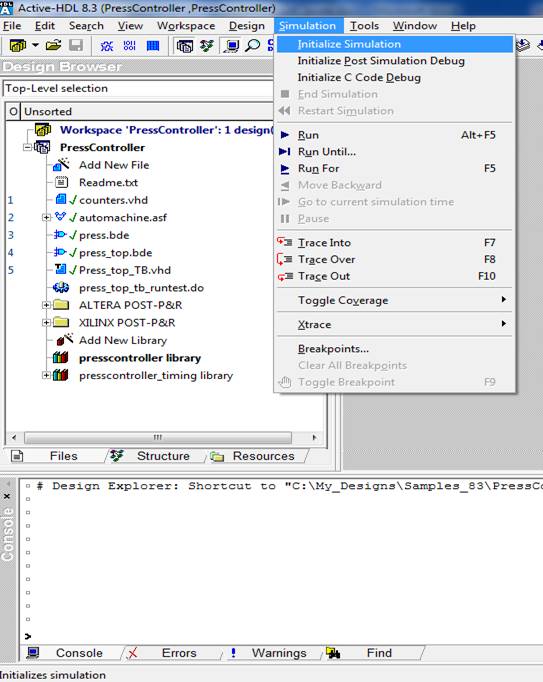
Figure 11 Initializing Simulation
You can run simulation for an unspecified amount of time. For that choose Run from the Simulation menu. To advance a simulation by a specific time step, set the desired time step in the Simulation Step box located in the main toolbar (see Figure 12). Choose Run For from the Simulation menu or choose Run Until from the Simulation menu. Specify the desired time until a simulation should run and then click OK.

Figure 12 Simulation Step box
PAUSE/End Simulation
To pause the simulation at the current simulation time, choose the Pause option from the Simulation menu.
To finish the simulation session, choose End Simulation form the Simulation menu.
You can restart the simulation, select Restart Simulation from the Simulation menu.
Waveform Viewer
Active-HDL offers two waveform viewers:
Accelerated Waveform Viewer presenting simulation data stored in the binary simulation database (*.asdb).
Standard Waveform Viewer/Editor displaying simulation results saved in the *.awf text file.
By default, the Accelerated Waveform Viewer is enabled and an *.asdb simulation database is created upon initialization of simulation. The Accelerated Waveform Viewer should be the pseered choice for designers working with large amounts of simulation data. It is optimized for large designs and long simulation runs.
The Standard Waveform Viewer/Editor is better suited for working with small designs, especially in the interactive mode. For example, it can show how the current simulation overwrites results from the previous simulation run and allows you to use hotkey stimulators.
Opening a new waveform file and adding signals
In order to open a new waveform window, go to New | Waveform from the File menu; click New Waveform on the toolbar.
Before you start any simulation you must select signals that represent the input and output ports of the tested model or internal signals. To add signals to the waveform file go to the Design Browser and on the Structure tab, click on the top level design file. Right-clicking on the top level design select Add to Waveform option. This option adds one or more selected objects to the waveform window (in order they are displayed in the Design Browser, order of selection, or order resulting from both manual object multi-selection and then adding the selected signals). You can also add all signals from the selected hierarchy and its sub regions by using the Add to Waveform Recursively option available in the context menu of the Structure tab. You can also add the signals by dragging objects from the upper or lower pane of the Structure tab to the waveform window (see Figure 13).
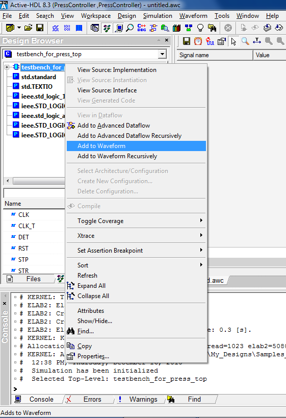
Figure 13 Adding Signals to Waveform Viewer
Saving the waveform file for off-line viewing
When the simulation is finished or has run for the given time, you can save the waveform using File | Save menu.
You can open saved .awc file for off-line viewing.
NOTE: Please stop the simulation before saving the waveform file.
Use the restart button to reinitialize the simulation without losing the signals in the waveform.
Saving the waveform file for reuse in successive simulations
The Waveform | Save to macro menu option or the File | Export menu command allow generating a macro (.do file) that can restore the view of the Waveform Viewer in your successive simulation runs and it contains a number of add wave or list commands for each signal found in the *.asdb file (see Figure 14).
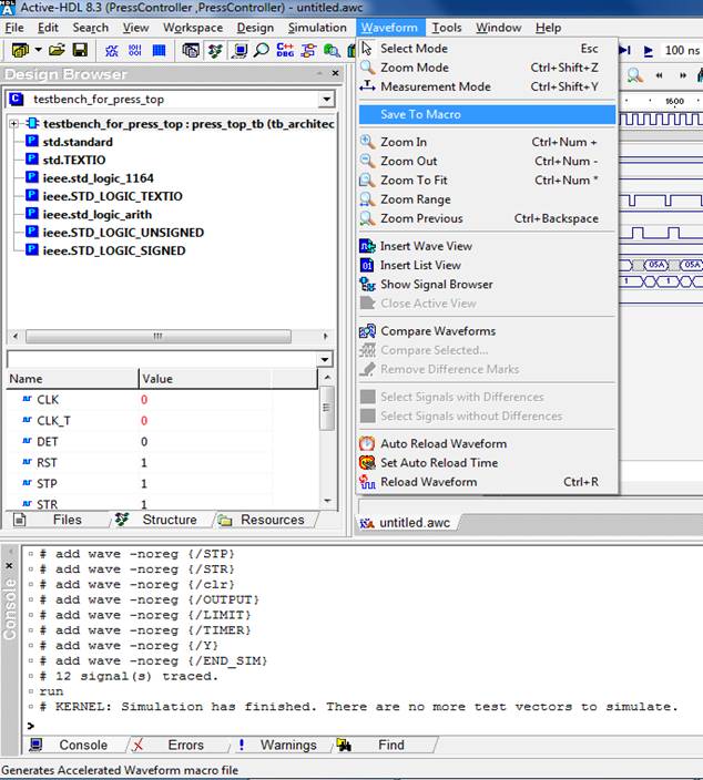
Figure 14 Save to Macro
Running a macro file
Saved macro file can be used later to add the signals on the waveform for another simulation run. You can execute this macro in your script immediately after you initialize your simulation.
Help
Within the tool
Go to menu Help | Product Help to learn more about Active-HDL.
Help on web
Go to www.aldec.com/support to access the online database and other technical documents about Active-HDL.
Support Account
Register or use your Aldec support account at www.aldec.com/support to open a support case or download the software.
Corporate Headquarters
2260 Corporate Circle
Henderson, NV 89074 USA
Tel: +1 702 990 4400
Fax: +1 702 990 4414
https://www.aldec.com
©2026 Aldec, Inc.